How API 650 storage tanks are designed: the engineering basics
API 650 tank design starts with the service conditions, not a plate thickness. A sound design links the stored product and operating envelope to materials, shell and bottom design, roof behaviour, connections, fabrication and inspection. This guide explains that workflow without replacing the licensed standard or a project-specific engineering calculation.
Section 011. Confirm that API 650 is the right design basis
API 650 addresses welded storage tanks within its defined scope. It is commonly associated with above-ground, vertical cylindrical tanks operating near atmospheric pressure, subject to the standard’s detailed limitations and applicable annexes. A pressure vessel, unusual geometry or service outside that scope needs a different or additional basis.
API announced the 14th edition in August 2025, with a March 2026 effective date for its Monogram programme. That programme date does not independently determine every project’s contract requirements. Confirm the edition, addenda and purchaser specification before calculations begin.
Section 022. Build a complete tank data sheet
The design basis should record working capacity, diameter and height, liquid density, design temperature, pressure and vacuum limits, corrosion allowance, roof type, site loading and material requirements. Empty, operating, test and maintenance conditions may govern different components.
For a Namibian coastal or mining project, obtain actual site data rather than assuming generic conditions. Wind exposure, ground conditions, product chemistry, corrosion environment and access influence the engineering scope.
- Product properties and credible operating extremes.
- Filling, withdrawal and venting duties.
- Foundation and settlement information from the responsible discipline.
- Nozzle duties, connected piping loads and maintenance requirements.
Section 033. Design the shell courses and bottom
Hydrostatic pressure increases with liquid depth. Consequently, lower shell courses generally experience greater liquid-head loading than upper courses. Thickness selection also depends on material strength, the permitted design method, corrosion allowance, testing conditions and minimum requirements.
Bottom and annular-plate details are assessed together with the shell-to-bottom connection and foundation interface. Uneven settlement can change structural behaviour; selecting thicker plates is not a substitute for understanding the supporting ground.
Section 044. Coordinate the roof, wind girders and openings
Roof type changes the load path and maintenance requirements. Roof plates, support framing and shell stability must be considered as a system. Wind girders and other stiffening details are designed where required by the applicable checks.
Nozzles and manways interrupt the shell or roof. Their reinforcement, weld details, access and connected piping loads require attention. A nozzle that fits on a drawing may still be unsuitable if the pipe support arrangement imposes loads the design has not considered.
Section 055. Address corrosion, venting and containment separately
Corrosion allowance must be justified for the product and intended service life. Coatings, linings or alternative materials may require specialist input. A generic allowance cannot demonstrate chemical compatibility.
Normal and emergency venting must be engineered for the operating scenarios using the applicable requirements; API 2000 may be relevant. Spill containment, fire protection, instrumentation and site environmental obligations are coordinated systems, not resolved by API 650 shell calculations alone.
Section 066. Turn calculations into an inspectable fabrication package
The handover should make materials, plate arrangements, weld details, tolerances, examination and test requirements traceable. Welding procedures, qualification requirements, fabrication sequencing and inspection planning are part of producing the intended asset.
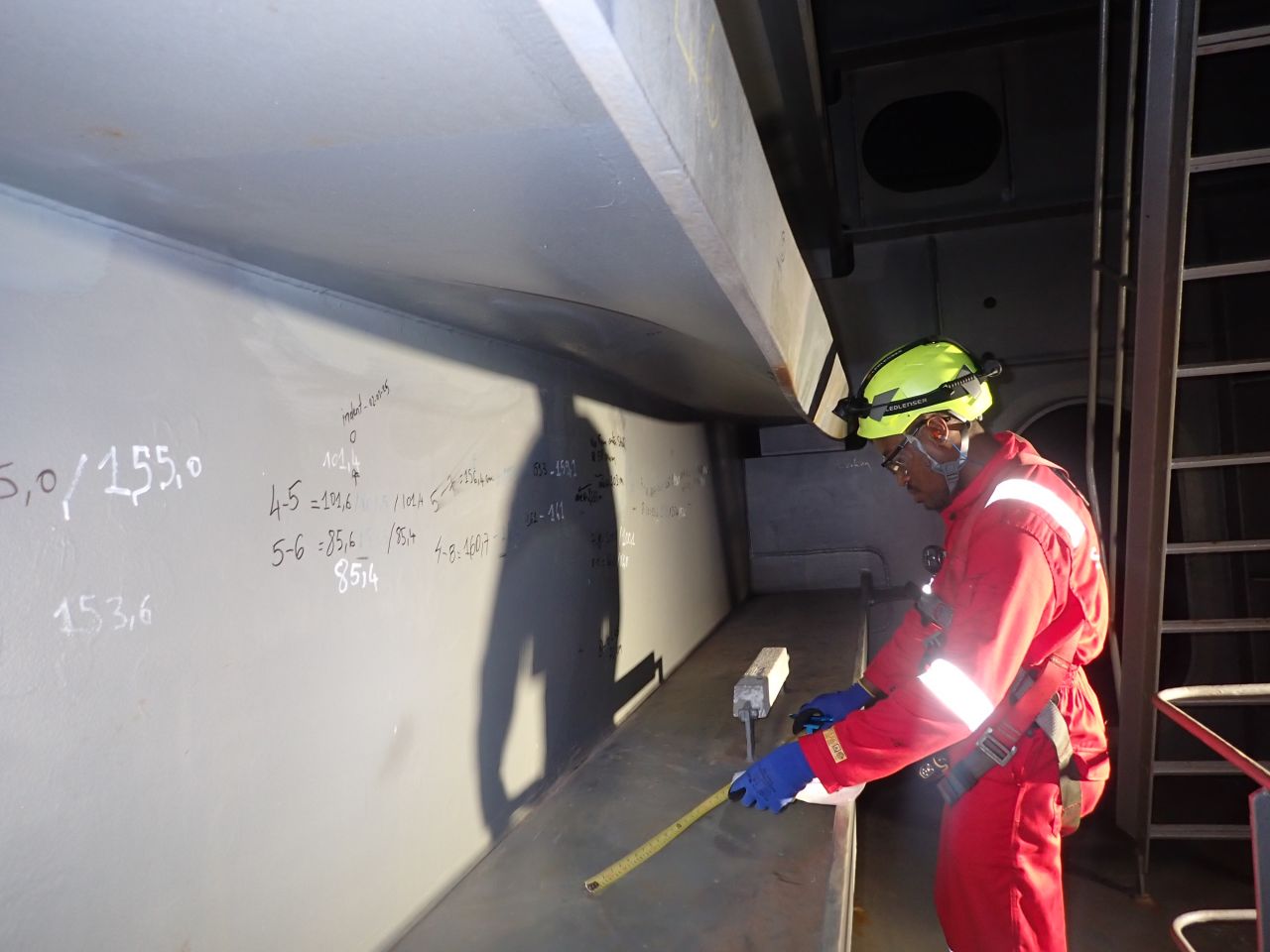
My Walvis Bay experience includes a nine-tank package covering heavy fuel oil, sludge and water, with bottom and annular plates, shells, wind girders, roof trusses and nozzles. That experience illustrates the breadth of a tank package, not a universal design template.
Section 07Questions to ask before commissioning a tank
Which edition and purchaser specification apply? Are product properties and venting duties confirmed? Who owns foundation design? How will the tank be inspected and maintained? Which deliverables and approval stages are included?
Do not select plate thickness, welding details or test pressures from this article. Final design requires the complete standard, verified project inputs and competent engineering review. Existing-tank assessment and repairs may require API 653 or other applicable requirements rather than simply repeating a new-tank design calculation.