Fabrication drawings and welding documentation: turning design into buildable work
A 3D model communicates shape, but a fabrication package must communicate how that shape will be built and verified. Steelwork, tanks and vessel systems need controlled geometry, materials and connection information. Unresolved details can become expensive site decisions.
Section 01Translate the design basis into drawing information
The analysis and drawings should describe the same structure. Show member or plate sizes, supports and connection details consistent with the calculation assumptions. A modelled fixed joint cannot be justified by a drawing that omits the relevant force-transfer detail.
My documented deliverables include fabrication drawings and welding procedures for tanks, FPSO storage structures and marine components. These are project-specific documents, not a claim that one generic drawing package applies to every fabrication job.
Section 02Control dimensions, tolerances and interfaces
State datums, orientation and the information needed to assemble components correctly. Coordinate mating parts, equipment connections and installation clearances. Distinguish final verified dimensions from those requiring a further survey.
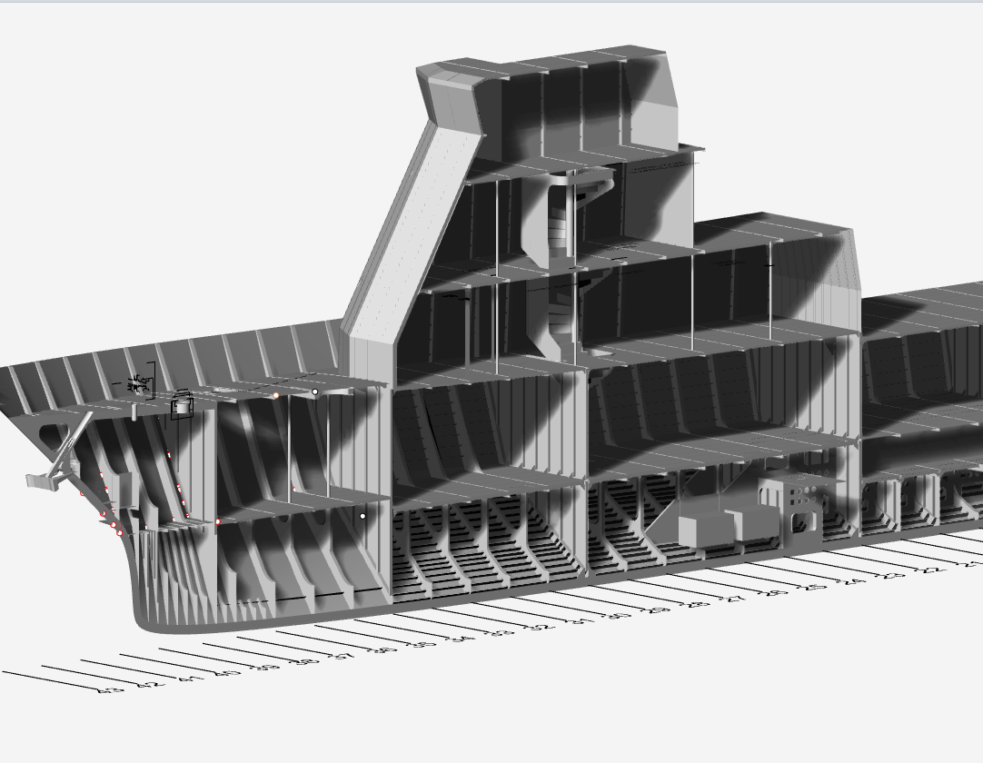
A fabrication shop in Walvis Bay should not have to infer hidden geometry from a rendered image. Use suitable views, details and schedules, and keep related models and drawings on compatible revisions.
Section 03Separate weld details from procedure qualification
Weld symbols and joint details communicate design requirements; a welding procedure specification addresses how welding is to be performed. Supporting qualification records and welder qualifications are separate requirements where applicable. A weld symbol does not qualify a procedure.
Materials, joint configuration and the governing standard influence the required documentation. Confirm responsibilities between designer, fabricator and inspection provider. Do not imply that a procedure is approved simply because it is included in a design package.
Section 04Specify inspection and change control
Agree inspection extent, acceptance basis, hold points and material traceability. The requirements should suit the component and project rather than copying a blanket inspection note. Inspection access needs to be considered while details are still being developed.
Changes to materials, dimensions or connections can affect the design. Establish a review process for fabrication queries and site deviations so informal substitutions do not undermine the engineering basis.
Section 05Deliver records that support the asset lifecycle
The final package should identify the issued drawing status, inspection records and reviewed as-built changes. Owner records support maintenance and later modification. A completed fabrication does not by itself demonstrate that every approval or acceptance requirement has been met.
- Verified geometry and design-consistent details.
- Materials and welding-document responsibilities.
- Inspection, traceability and hold points.
- Controlled revisions and as-built handover.