3D laser scanning offshore: planning a survey for usable engineering data
A dense point cloud is not the same as a verified as-built model. Offshore 3D laser scanning needs a clear engineering purpose, sufficient coverage and documented uncertainty. For Namibia-based teams supporting marine assets, the survey should capture the interfaces that control fabrication and installation.
Section 01Define the deliverable before collecting data
Decide whether the output is a dimensional report, deformation comparison, replacement-spool model or coordinated layout. Each requires different coverage and tolerances. Capturing an entire compartment does not ensure that a concealed flange face or support interface is usable.
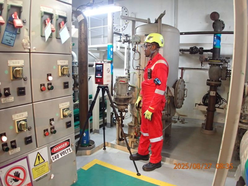
My offshore work has used Riegl VZ-600i scanning for geometry capture, including hull deformation and pipe replacement areas. The tool supports the survey; the engineering brief determines what must be measured and checked.
Section 02Plan datums, registration and line of sight
Scan positions must address obstructions, restricted access and the surfaces needed for the design. Establish reference geometry and a coordinate convention that can be communicated to the office and fabrication team. Registration joins scans but does not eliminate every measurement uncertainty.
Reflective, wet or difficult surfaces may produce incomplete data. Moving equipment, vibration and changes between visits can also complicate comparisons. Record the conditions and distinguish scan-derived geometry from separately verified dimensions.
Section 03Check interfaces rather than trusting visual detail
Replacement pipework may need flange orientation, bolt-hole alignment and support locations. Structural repairs may need plate boundaries, offsets and connection access. These details can control whether a fabricated component fits even when the overall model looks convincing.
Use independent measurements where the required tolerance or visibility makes them necessary. A model should not invent hidden geometry without clearly marking it as assumed. Record areas where access prevented verification.
Section 04Manage point clouds and design models separately
The captured point cloud is evidence; the interpreted CAD model is an engineering deliverable. Document how dimensions were extracted, which surfaces were simplified and how model revisions relate to the field data. Keep the original survey information available for review.
A scan does not establish material grade, wall thickness, weld quality or remaining structural strength. Pair geometry capture with the relevant inspection programme when corrosion or integrity is part of the scope.
Section 05Make the handover useful offshore and ashore
Agree file formats, units, coordinates and revision controls before mobilisation. A yard in Walvis Bay and an offshore installation team must be able to use the same dimensional references. The report should describe the survey’s limitations as clearly as its coverage.
- Survey purpose and required tolerances.
- Reference system and registration checks.
- Verified interfaces and inaccessible zones.
- Point cloud, model and drawing revision relationship.