Hull deformation surveys: measuring distortion before reinforcement design
A distorted hull plate or stiffener needs investigation before a reinforcement detail is selected. Geometry tells the engineer where deformation exists; inspection and operating history help explain what it means. Repair design must address the cause and the surrounding structural system.
Section 01Establish a reference for the deformation
Define what the measured surface is being compared with: verified original geometry, a design model or a suitable reference region. Record the vessel condition and survey datum. An apparent offset may include original fabrication variation or differences in measurement conditions.
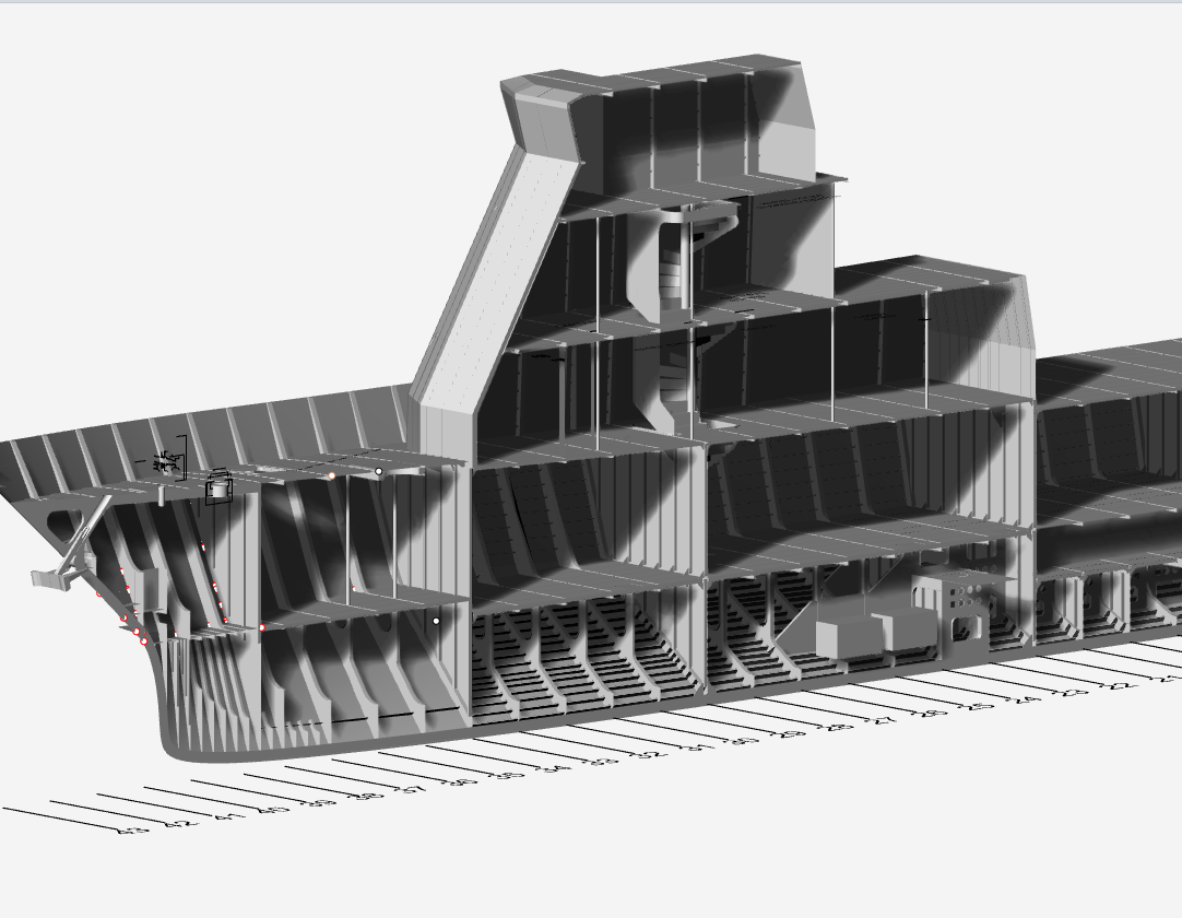
My Kaombo Sul FPSO work included scanning to map hull deformation and gusset-reinforcement fabrication drawings. The portfolio cutaway image illustrates vessel structure; it is not a defect map or an image of that specific repair.
Section 02Pair geometry with integrity information
Look for corrosion, cracking, damaged connections and relevant loading history. Scan data cannot determine wall thickness or weld quality. Inspection should address the suspected mechanism and the components that transfer loads through the area.
A deformed component may have redistributed loads to adjacent members. Document nearby supports, stiffeners and boundaries so the engineering assessment does not focus only on the most visible plate.
Section 03Assess cause and structural consequence
Possible drivers include overload, restraint, impact, loss of support or deterioration; a website description cannot diagnose an individual asset. The assessment must determine whether the current geometry affects capacity, stability, watertight boundaries or equipment interfaces.
Class or owner requirements may govern the repair review. Distinguish an engineering proposal from approval and identify any additional survey or analysis required before construction.
Section 04Detail reinforcement as a load-transfer system
A gusset changes stiffness and transfers force into adjoining structure. Its dimensions, terminations, welds and support conditions need to match the analysis. Adding steel without checking the receiving members can create local stress concentrations or shift failure elsewhere.
Access for fabrication and inspection matters. Where repair work affects tank boundaries or introduces hot work, the authorised isolation, entry and work-control requirements must be part of the project planning.
Section 05Close out the repair with evidence
Fabrication drawings should show the verified geometry, material and connection requirements. Define inspection and post-repair checks with the responsible parties. Record as-installed differences and any monitoring needs rather than assuming the drawing describes the final condition.
- Survey reference and deformation mapping.
- Condition and cause investigation.
- Reviewed load path and reinforcement detail.
- Inspection, as-built records and follow-up actions.