Industrial roof covers in Walvis Bay: wind, supports and maintenance access
An equipment roof cover may look simple, but wind uplift and its support interfaces can control the design. Industrial covers must protect equipment without blocking operation or maintenance. Coastal exposure adds durability considerations that need an actual project assessment.
Section 01Define the protection and operating requirements
Confirm what the cover is intended to protect and what access the equipment requires. Mixing tanks, compressors and their services can have different clearance, ventilation and maintenance needs. The roof layout should be coordinated with equipment suppliers and the operating team.
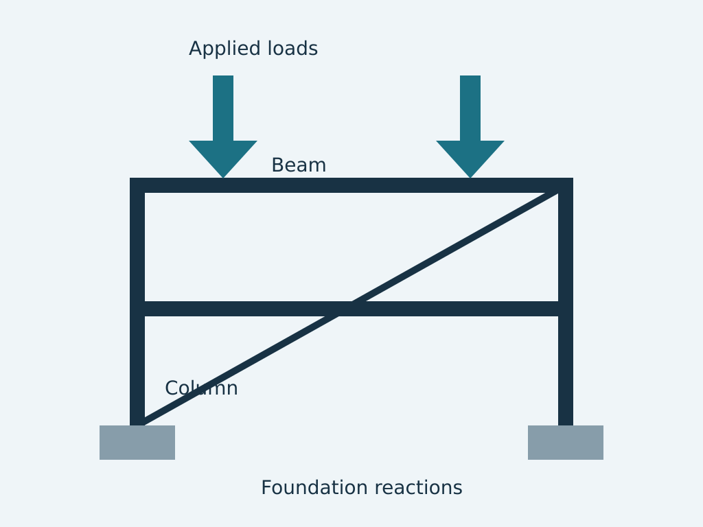
My Walvis Bay design portfolio includes mixing-tank and compressor roof covers with fabrication drawings. This article explains general design coordination; the diagram is educational and does not show a completed cover or a standard reusable solution.
Section 02Assess wind and other loading
Site location, exposure, roof geometry and openings affect wind actions. Uplift can govern cladding fixings and support reactions. Do not assume that self-weight is sufficient to hold down a lightweight cover.
Other relevant actions may include maintenance loads, services and rainwater-related conditions. Confirm the applicable combinations and design standard. Generic coastal wind assumptions should not replace verified site inputs.
Section 03Trace loads into verified supports
Columns, brackets, base plates and anchors transfer roof reactions into their receiving structure. An existing tank or equipment frame should not be treated as a support without checking suitability and obtaining the responsible designer’s agreement.
Consider installation tolerances and movement. Details that restrain equipment unexpectedly or obstruct access can create problems even where individual member calculations are satisfactory.
Section 04Coordinate drainage and durability
Water traps, inaccessible connections and dissimilar-material interfaces can complicate corrosion management. Protective systems should match assessed exposure and a realistic maintenance strategy. A coastal location does not justify an arbitrary coating specification without further information.
Arrange drainage and access so inspections and future repairs are practical. Cladding and fixings are part of the design, not details to leave unresolved after the steelwork is fabricated.
Section 05Make fabrication and installation requirements explicit
The drawing package should define members, connections, cladding interfaces, materials and relevant inspection. Coordinate lifting and assembly with the yard or site team. Clearly state where final dimensions depend on a verified equipment survey.
- Equipment clearances and maintenance envelope.
- Wind and other design actions.
- Verified support and anchor interfaces.
- Drainage, protection and fabrication details.