Truck-ramp structural design: why vehicle mass is not the full load case
A truck ramp is loaded through tyres and supports, not through a perfectly uniform pressure. Structural design needs the vehicle geometry, use conditions and handling requirements. The headline vehicle mass is only one input in a design that must also be fabricated, moved and maintained.
Section 01Define the vehicles and intended use
Confirm axle loads, wheel spacing, tyre contact information and relevant operating conditions. Loading changes as the vehicle moves across the ramp. Braking, transitions and other actions should be addressed where required by the agreed design basis.
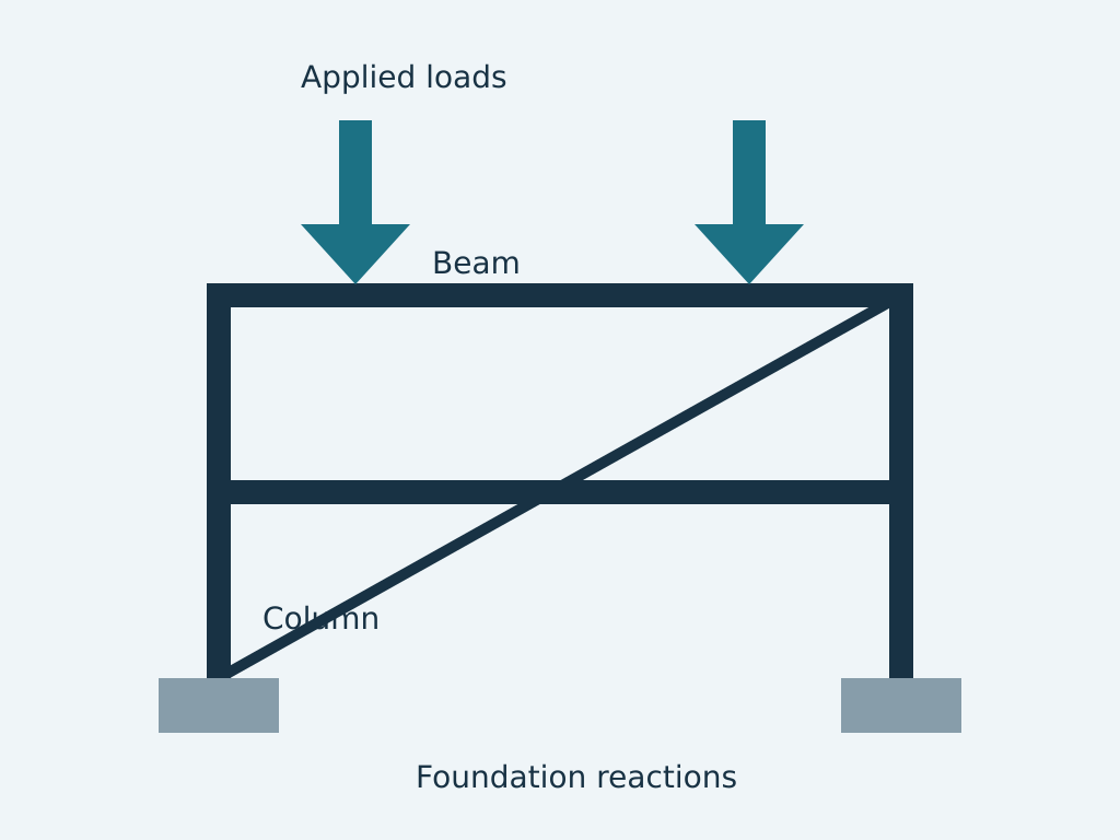
My Walvis Bay portfolio includes a 30-tonne truck ramp with lifting lugs and forklift pockets. That documented project rating must not be transferred to another ramp without its own analysis. The educational diagram shows load paths, not the original project drawing.
Section 02Check geometry and contact conditions
Ramp slope, transitions, clearances and the supported vehicle determine whether the arrangement is usable. Structural adequacy alone does not establish safe vehicle access. Operating restrictions and traction requirements need agreement with the owner.
The deck must distribute local wheel loads into stiffeners and main members. A calculation using only an evenly spread payload can miss the governing plate or member condition.
Section 03Design supports and connections
Trace loads through the deck, beams and supports to the ground or receiving structure. Check the assumed contact and restraint conditions against what will actually be installed. Stability and support settlement may affect both structural performance and alignment.
Connections, end details and local bearing areas require their own checks. A convenient member size does not compensate for an unsupported plate edge or inadequate connection.
Section 04Include lifting and forklift handling
A ramp can be structurally adequate in service but vulnerable while being moved. Lifting lugs and forklift pockets introduce different load paths and local actions. Confirm the handling configuration, equipment interfaces and centre of gravity.
Do not imply that an integrated lug is certified merely because it appears on a fabrication drawing. Testing, inspection, marking and operating procedures depend on the agreed equipment requirements.
Section 05Issue a complete fabrication package
Drawings should identify materials, deck arrangement, welds, handling points and the required finish. State design assumptions and use limits in appropriate documentation. A Walvis Bay yard needs clear dimensions and inspection requirements, not just a rendered model.
- Vehicle and wheel-load schedule.
- Ramp geometry and support basis.
- Service and handling load cases.
- Fabrication details, inspection and operating limits.