Lifting beams and padeyes: designing the complete lifting load path
A lifting beam, shackle and padeye are parts of one load-transfer system. Designing only the visible beam leaves important interfaces unchecked. For onshore and offshore lifting projects supported from Namibia, establish the lift configuration, equipment basis and approval responsibilities before selecting details.
Section 01Define the lifting configuration
Confirm the lifted mass, centre of gravity, attachment locations and proposed arrangement. Account for the applicable dynamic and other design effects through the agreed standard rather than assuming that a nominal payload is the complete design load. Uneven load sharing may matter.
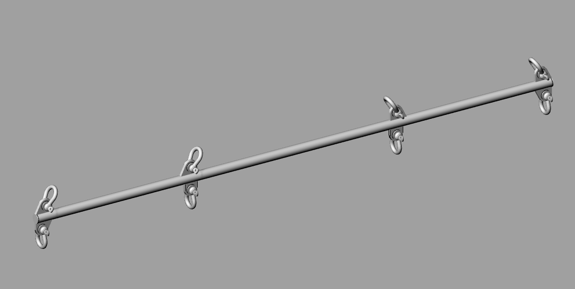
My documented work includes lifting beams, lifting lugs and padeyes in Namibia and Angola. The portfolio model shows an example arrangement; it is not a certified drawing or a statement of rated capacity for equipment supplied through this website.
Section 02Understand beam and sling behaviour
A spreader and a lifting beam can have different force distributions depending on their arrangement. Sling angles change the forces in attachments and members. The analysis should represent the actual configuration, including restraints, eccentricities and credible misalignment.
Check strength, stability and the relevant serviceability requirements. A beam that satisfies a simple bending calculation may still be limited by buckling, a connection or the geometry of its lifting points.
Section 03Check padeyes and the receiving structure
The lug plate, hole region, welds and supporting member need a coordinated assessment. Shackle compatibility and the direction of force must be verified. A satisfactory isolated lug calculation does not demonstrate that the deck, frame or weld supporting it can receive the load.
Fabrication access, inspection coverage and edge details influence the practical design. Reused lifting points need condition verification and a suitable assessment basis; paint markings alone do not establish integrity or rating.
Section 04Specify manufacture and verification
Controlled drawings should identify materials, dimensions, connections and inspection requirements. Applicable testing, marking and certification responsibilities must be agreed with the owner and competent parties. Design approval and equipment certification are distinct from a model or calculation package.
Avoid treating a generic test multiplier as a universal rule. The governing equipment standard, class requirements and intended use determine the verification programme.
Section 05Coordinate the lifting operation separately
An equipment design does not replace a reviewed lifting plan. The operation also needs competent planning, crane capacity checks, rigging selection, site controls and communication responsibilities. Changes to mass, centre of gravity or sling arrangement should trigger engineering review.
- Verified load and centre of gravity.
- Defined configuration and design standard.
- Member, connection and support checks.
- Manufacture, inspection and lifting-plan interfaces.