Rotating crawler beams: checking the moving load and supporting structure
A rotating crawler beam changes the load position as equipment moves and the beam rotates. The design must cover the operating envelope, not just one convenient configuration. Trolley, hoist, rotation mechanism and supporting structure need a coordinated assessment.
Section 01Define the movement envelope
Confirm the intended rotation range, trolley travel, lifted load and operating restrictions. Identify clearances, access and potential clashes throughout the movement. The equipment should not be assessed only at its parked position.
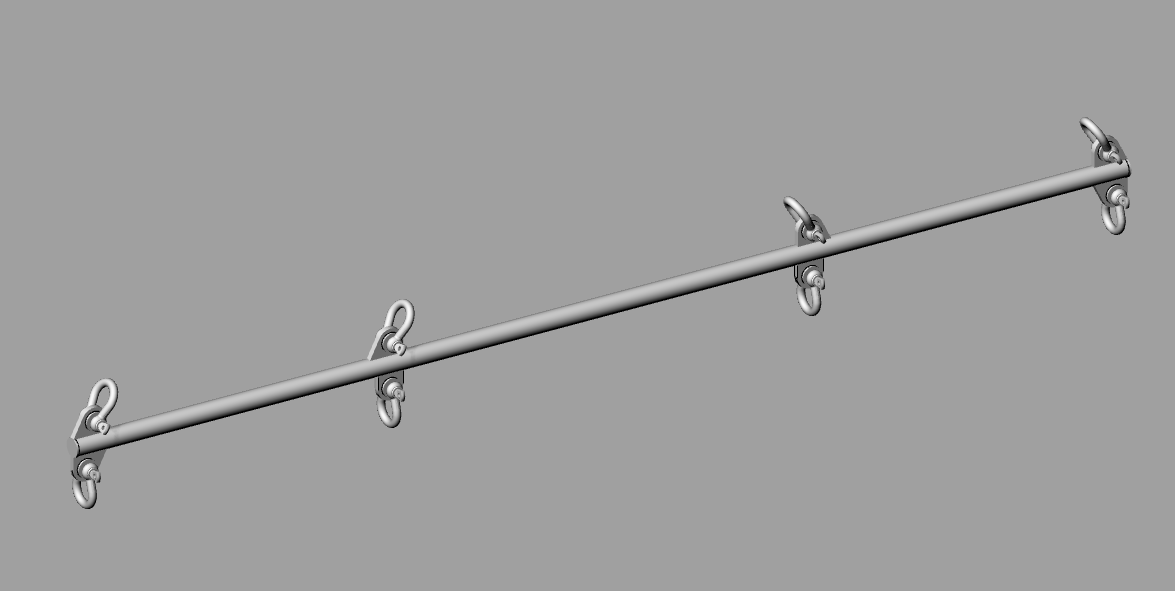
My documented Luanda project included a rotating crawler beam with 180-degree rotation and a 2-tonne SWL. Those values describe that project scope and are not a specification or rating for the illustrative model shown here.
Section 02Assess the governing load positions
Moving loads alter bending, shear and reactions. The most demanding position for a member may differ from the most demanding position for a connection or support. Include relevant dynamic and other effects through the agreed design basis.
Lateral restraint and local trolley contact conditions can matter. A general beam calculation does not automatically verify the flange, track interface or compatibility with the selected lifting equipment.
Section 03Verify rotation and support details
The rotation mechanism and its connections transmit loads into the receiving structure. Assess the full range of reactions, including effects that change direction during movement. Confirm that the assumed support stiffness and restraints exist in the installed arrangement.
Review the existing structure’s condition and available capacity. An apparently strong mounting point may still be unsuitable because its local plate, welds or adjoining members were not designed for the new actions.
Section 04Coordinate equipment and operating controls
Trolley, hoist, stops and other equipment must be selected and integrated for the intended use. Define relevant limits and review responsibilities with the equipment supplier and owner. A drawing cannot substitute for competent operation and inspection.
Manufacture, testing, marking and certification requirements should follow the applicable standard and project specification. Do not copy a generic proof-test value into the package without establishing its basis.
Section 05Keep the lifecycle records traceable
The handover should connect the reviewed design to the as-installed equipment, inspection records and use restrictions. Changes to the load, travel or rotation limits can invalidate assumptions and need assessment. For Namibia-supported offshore work, agree who retains and updates these records.
- Load and movement envelope.
- Member, trolley and connection checks.
- Receiving-structure verification.
- Testing, inspection and operating responsibilities.