Ballast-tank reinforcement beneath a helideck: tracing the support loads
Helideck loads do not stop at the deck surface. They pass through supporting members and into the rig or vessel structure, which may include members inside ballast tanks. Reinforcement needs a verified load path, measured condition and a clear repair review process.
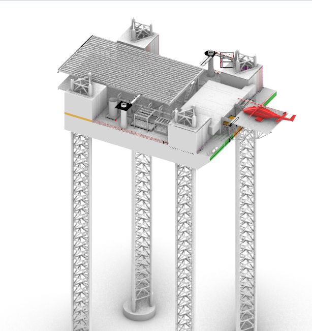
Section 01Map the complete supporting system
Identify deck supports, columns or stools, underlying frames and the structure that receives their reactions. Drawings and field measurements must establish how these components connect. A local member check does not demonstrate that the entire support path is adequate.
My Abidjan oil-rig work included ballast-tank reinforcement supporting a helideck. This is a specific reinforcement-design scope, not a claim that every rig uses the same support arrangement or that a design guide constitutes aviation approval.
Section 02Use the measured condition
Ballast spaces may have coating deterioration, local thinning or restricted inspection access. Determine which members and connections require examination and how nominal geometry differs from the current condition. Inspection limitations should remain visible in the assessment.
A thickness survey alone may not resolve cracking or connection behaviour. NDT methods should be selected for the suspected defects and carried out under appropriate procedures by qualified personnel.
Section 03Confirm loading and applicable requirements
The helideck design basis must address the specified aircraft, landing actions and other applicable loads. Supporting-structure checks should use the relevant combinations and verified boundary conditions. Do not substitute a generic uniform load for the required aviation and structural assessment.
The owner, class and aviation requirements must be coordinated for the actual asset. A reference to DNV or another organisation is not itself evidence of approved design or operational acceptance.
Section 04Design reinforcement and execution together
Reinforcement changes local stiffness and transfers forces through new connections. Verify the receiving structure, connection design and details at terminations. Welding access, inspection coverage and coating restoration influence whether the proposed detail can be installed and maintained.
Confined-space entry, gas testing, isolation and hot-work controls are managed through the asset’s authorised systems. Engineering drawings should identify constraints; they do not replace these procedures.
Section 05Document the reviewed final condition
Handover should include the design basis, inspection inputs, controlled drawings and installation records. Capture deviations and confirm their engineering review. Continued inspection access is important where the reinforced area remains exposed to ballast service.
- Verified helideck-to-hull load path.
- Condition data for supports and connections.
- Project-specific loading and approval interfaces.
- Installation quality records and future inspection access.