Onshore structural engineering in Namibia: from industrial brief to steel design
Onshore industrial structures need an engineering basis that reflects their actual use. Warehouses, roof covers, platforms and equipment supports have different loading and interface requirements. For a Namibian project, good structural engineering connects the operating brief to analysis, foundations and fabrication-ready information.
Section 01Define the structure and its operating environment
Start with the intended use, location, equipment layout and required design life. Identify whether the scope is a new structure, an extension or an alteration to an existing asset. Gather available drawings and establish what must be verified by survey.
My documented onshore design experience includes warehouse structural design, mixing-tank and compressor roof covers, a truck ramp and industrial tanks. Other heavy-industry applications discussed here are educational engineering topics, not additional claims of completed projects.
Section 02Agree loading and the applicable design basis
Define permanent, imposed, wind and other relevant actions using verified project inputs. Industrial equipment can introduce concentrated, cyclic or dynamic loads that are not represented by a generic building floor load. Maintenance and installation cases may also require assessment.
Confirm standards, editions, client specifications and review responsibilities with the project team. A reference to Eurocodes or another international source is educational; it does not establish which standard is legally required or accepted for every Namibian project.
Section 03Trace loads through a stable structural system
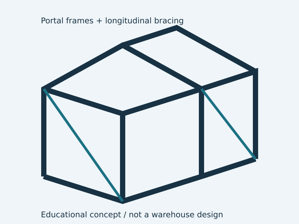
Beams, columns, bracing and connections should form a continuous path to the foundations. Analysis assumptions must reflect actual restraints, member geometry and connection behaviour. Check stability and relevant deformation limits as well as member strength.
Coordinate foundation reactions with the responsible foundation designer and verified ground information. A heavier steel section does not fix an inadequate anchor arrangement, missing bracing or unsuitable foundation assumption.
Section 04Coordinate design with fabrication and installation
The design must be practical for available fabrication, transport and erection arrangements. Member splices, lifting interfaces, connection access and inspection coverage affect the final details. Review these constraints before drawings are released.
For projects in Walvis Bay, Swakopmund or Windhoek, obtain actual site and logistics information rather than repeating a standard local assumption. Durability, maintenance access and equipment interfaces can differ significantly between coastal and inland sites.
Section 05Deliver a traceable engineering package
Define the required calculations, drawings, specifications and review status at the start. A structural model is not a fabrication release, and a completed drawing is not evidence of an unperformed approval. Record assumptions, unresolved interfaces and later changes clearly.
- Agreed design brief and loading schedule.
- Analysis, member and connection checks.
- Foundation reactions and discipline interfaces.
- Controlled fabrication drawings and review responsibilities.
Related
- Onshore, industrial and offshore structural engineering in Namibia
- Steel warehouse and portal-frame design: bracing, connections and serviceability
- Steel fabrication planning in Namibia: design release, tolerances and erection
- Industrial equipment supports: designing steelwork around real machine loads