Steel warehouse and portal-frame design: bracing, connections and serviceability
A warehouse frame is more than a row of columns and rafters. The building’s stability depends on how those frames interact with bracing, cladding interfaces and foundations. Industrial warehouse design needs a verified arrangement and load basis before section sizes can be selected.
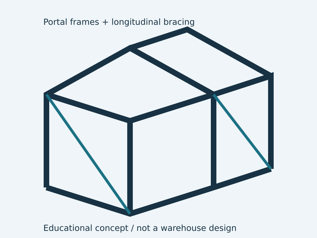
Section 01Establish the building layout and functional requirements
Record span, height, bay spacing, openings and the operating layout. Storage arrangements, services and future changes may affect the design. Clearances for vehicles and equipment should be coordinated with the owner rather than assumed from a concept sketch.
Warehouse structural design is part of my documented portfolio. The diagram accompanying this guide illustrates framing concepts only; it is not a photograph of a completed warehouse or a structural calculation for a particular site.
Section 02Understand frame action and stability
A portal frame relies on the intended stiffness of its members and connections. The analysis must include suitable assumptions about joint behaviour, restraints and second-order effects where required. A nominally rigid joint needs details that can provide the modelled force transfer.
Longitudinal bracing transfers actions between bays and into supports. Openings or equipment layouts can interrupt a convenient bracing arrangement. Identify the complete lateral system early instead of leaving it to the fabricator.
Section 03Assess site loading and serviceability
Wind pressure and uplift depend on site exposure, building geometry and opening conditions. Roof and wall systems need compatible design information. Do not treat a generic Namibia wind value as sufficient without confirming the applicable basis.
Deflection and movement can affect cladding, doors and equipment interfaces even if strength checks pass. Set serviceability criteria with the project team. A building used for heavy industry may need additional equipment loads or separate supporting structures.
Section 04Coordinate connections, bases and foundations
Eaves, ridge, splice and base details must transmit the forces assumed in the analysis. Base restraint should be consistent with both the steel connection and foundation design. Coordinate reactions, anchor layout and relevant tolerances with the responsible parties.
Cladding rails, purlins and their connections are not merely cosmetic additions. Their load-transfer and restraint functions need verification, including the assumptions used to restrain primary members.
Section 05Plan fabrication, erection and future modifications
Temporary stability during erection can differ from stability in the completed building. The erection contractor and engineer should identify the required temporary works and review interfaces. Future extensions or suspended equipment should trigger reassessment rather than reliance on an old drawing.
- Functional layout and site design basis.
- Primary frames and longitudinal stability.
- Connection, cladding and foundation interfaces.
- Fabrication, erection and change-control information.