Bolted and welded steel connections: making the analysis match the fabrication
A structural analysis assumes that connections transfer particular forces with particular stiffness. The fabrication details must provide that behaviour. Bolted and welded joints need coordinated design, manufacture and inspection; choosing a bolt diameter or weld symbol is not the complete assessment.
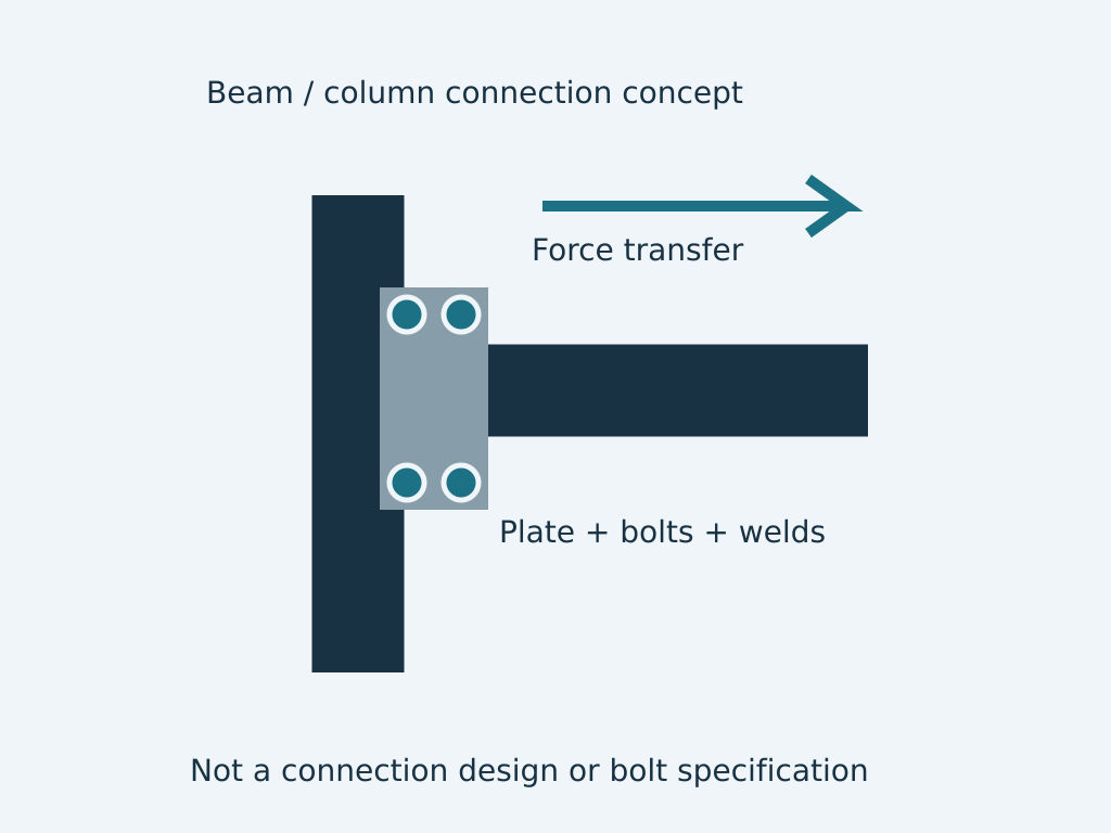
Section 01Start with forces and intended joint behaviour
Establish the actions at the joint, including relevant moments, shear, axial forces and eccentricities. Identify whether the analysis assumes a pinned, rigid or other defined behaviour. Connection details and model assumptions must be consistent.
A beam may pass its member checks while the connection governs the arrangement. Conversely, an unnecessarily rigid joint can introduce actions that were not allowed for in adjoining members or foundations. Review the whole load path.
Section 02Assess bolted connections as assemblies
Bolts, plates, holes and the connected members work together. Relevant limit states depend on the joint configuration and governing standard. Material grade, hole arrangement, edge distances and the specified bolt installation method influence the design.
Do not assume every bolt is interchangeable because its nominal diameter matches. Installation, tightening, inspection and access requirements must be specified for the intended connection. Site fit-up should not depend on unreviewed hole enlargement or other improvised changes.
Section 03Design welds and their receiving material
A weld must transfer force into suitable parent material with a compatible detail. Access, joint preparation and fabrication sequence affect practicality. A larger weld does not automatically solve inadequate plate behaviour or an unsuitable termination.
Weld details, welding procedure requirements and welder qualifications serve different purposes. The designer and fabricator should agree responsibilities and the applicable standards. Inspection requirements must reflect the actual component and joint rather than a generic note.
Section 04Consider tolerances and erection conditions
Shop and field connections may have different access and quality-control constraints. Coordinate transportable sections, temporary supports and assembly clearances. The connection should be buildable without compromising the intended force transfer.
A conceptual connection illustration is not a fabrication instruction. Final dimensions and specifications require project-specific calculations and review. For Namibian steelwork, early fabricator input can identify practical limitations before the drawing is released.
Section 05Control changes and preserve traceability
Material substitutions, revised bolt groups or altered weld details can change capacity and stiffness. Use a controlled query and review process. Retain the approved drawing, inspection records and as-built changes so future engineers can assess the actual joint.
- Joint forces and stiffness assumptions.
- Plate, bolt, weld and member checks.
- Fabrication access and installation requirements.
- Inspection, substitutions and revision control.
Related
- Fabrication drawings and welding documentation: turning design into buildable work
- Steel warehouse and portal-frame design: bracing, connections and serviceability
- Steel fabrication planning in Namibia: design release, tolerances and erection
- Onshore, industrial and offshore structural engineering in Namibia