Crane-supporting industrial steelwork: repeated loading and runway interfaces
Crane-supporting steelwork needs a design basis that reflects moving and repeated equipment actions. Runway beams and their supports are not ordinary roof beams. This educational guide identifies the inputs and interfaces industrial project teams should resolve before commissioning a design.
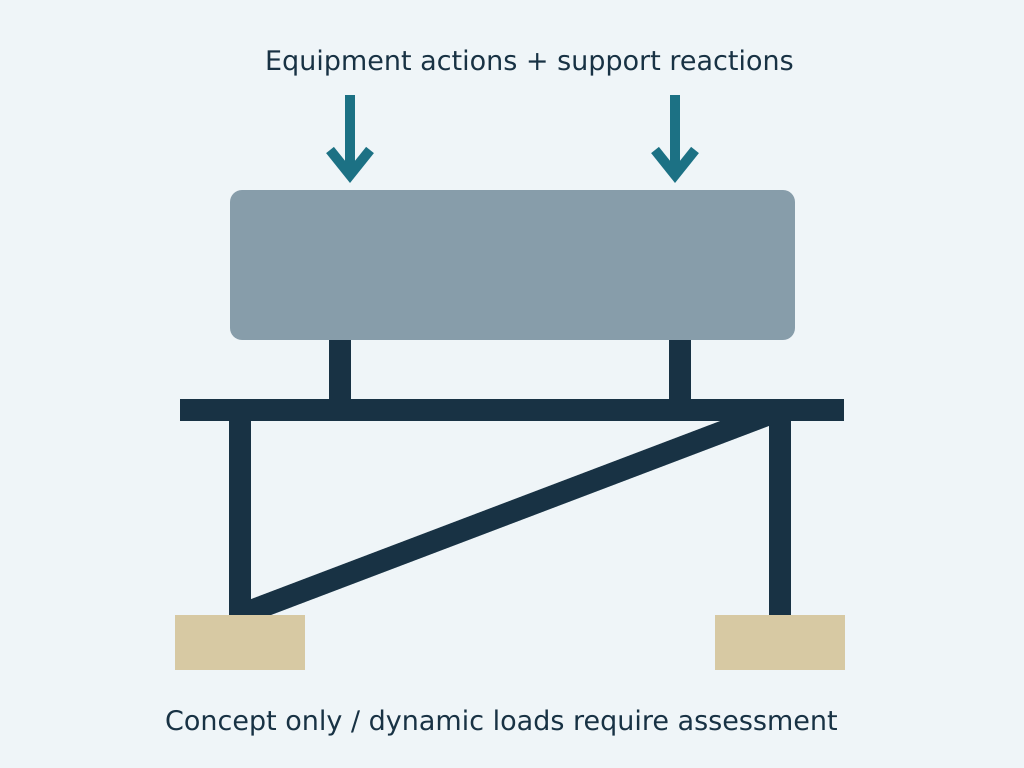
Section 01Obtain the crane supplier’s verified data
Confirm wheel loads, wheel spacing, operating duty and relevant horizontal or dynamic actions with the supplier. Identify credible operating configurations and maintenance conditions. The crane’s rated lifted load is not the complete load on the supporting steelwork.
This article covers an educational heavy-industry topic, not a claim of a completed overhead-crane runway project. My documented lifting-related experience includes lifting beams, padeyes, a rotating crawler beam and crane or davit bases, which have their own distinct design requirements.
Section 02Assess repeated actions and relevant limit states
Moving load positions change forces in beams, supports and connections. Repeated actions may require fatigue assessment under the applicable design basis. The equipment duty and stress ranges need proper definition rather than being replaced by a generic additional percentage.
Local load introduction and member stability require attention alongside global strength. Details and restraints must match the analysis. A stronger nominal section does not necessarily address a fatigue-sensitive connection or an inadequate support arrangement.
Section 03Coordinate alignment and serviceability
Equipment suppliers may specify alignment and movement limits. The building and runway support system must be assessed against the relevant criteria. Support deflection and foundation movement can affect equipment operation even when strength checks are satisfactory.
Tolerances need to be coordinated between steel fabrication, erection and equipment installation. State the survey and verification responsibilities; an attractive model cannot demonstrate the installed track alignment.
Section 04Review the building and foundation interfaces
Crane reactions can affect columns, bracing, connections and foundations. Trace the actions through the complete system. A warehouse frame designed without crane loading should not receive a runway addition without an appropriate assessment.
Maintenance access, end restraints and equipment interfaces require coordinated responsibilities. Confirm the applicable structural and equipment standards and the required review process with the owner and competent specialists.
Section 05Plan manufacture and lifecycle inspection
The design package should define controlled details and the necessary inspection requirements. Future changes in crane duty, capacity or layout should trigger review. Industrial operators in Namibia should retain supplier data, reviewed drawings and as-built records together so later modifications have a reliable starting point.
- Supplier loads and operating duty.
- Moving-load, stability and fatigue assessment.
- Alignment and building-support interfaces.
- Fabrication verification and lifecycle records.